CDI UNIT ASSEMBLY BOX IGNITION ET950 SCHEMATIC CIRCUIT DIAGRAM
1969-1978 Honda 500 550 750 Ignition CDI Unit ECU ECMU. Fig1b shows a typical CDI system which uses a DC-to-DC inverter to charge a capacitor which typically has a value of lµF.

Cdi Wiring Diagram Motorcycle Wiring Kill Switch Electrical Wiring Diagram
Pinout Diagram of the DC CDI.

. Built-in electrolytic capacitor for kick-start. VMC Chinese Parts 2195. The block diagram of CDI shown below.
Power for the circuit is derived from the ignition switch. Look at the circuit diagram of CDI of C90 Honda. This 12V supply is also directly used for other parts of the circuit.
Compatible with all types of control such as ignition and vehicle load controlled by onboard CPU. The CDI ignition systems therefore allow the engine to keep running as long as there is a charge in the power source. Refer to ILLUSTRATED SYMBOLS.
Circuit diagram of electronic ignition for old cars. Ignition coil distributor and spark plug is similar to previous. Meanwhile on the other side of the coil.
Effectively if your 2 stoke revs to say 8000 rpm its going to be sparking at 8000 x 2 16000 rpm. How it works. 1969-1978 Honda 4 Cylinder 750 Module Ignition Control CDI Unit.
Magneto Stator Coil Generator Yamaha Et650 And Et950 Motor Engine. Then the magnetic field cuts the charging coil core. No spark poor spark or performance.
Use a proper heat-sink for power transistor C4424 T2. Ignition systems that use a DC powered ignition box are pretty rare. A schematic diagram of an electronic ignition system is shown in Figure 236.
CDI - 5 Wire - 50cc 70cc 90cc E-Ton ATV - Version 39. The green LED LED2 connected in the output section lights up with back emf and therefore it should be connected with reverse polarity as shown in Fig. These three circuits show the three types of ignition circuit.
9 To help identify parts and clarify procedure steps there are exploded diagrams at the start of each removal and disassembly section 3. For example it is used for the points trigger circuit and the 100Ohm base resistor for Q1. Even so we get a lot of questions about how to troubleshoot them.
I bet you will be better off to take one of your old coils and rebuild it with some heavy duty enamel wire and then put it all in epoxy again. TECHNICAL INFO WIRING DIAGRAMS for FIREPLUG CDIs Still Having issues. VMC Chinese Parts 1425.
6 Pin Cdi Box Wiring Diagram 6 pin cdi box wiring diagram 6 pin dc cdi box wiring diagram Every electric structure is made up of various unique components. We hope youll find our diagram valuable in your repair efforts. That is why we have assembled the MSD Ignition Wiring Diagrams and Tech Notes.
A number indicates a dis-assembly step 4. The most notable difference between this system and the. The construction of the battery ignition switch.
Some things to check. Restoration Yamaha Rd125 A Yamaha Rd125 Specifications. 9 Symbols indicate parts to be lubricated or replaced 5.
300440550 650 wiring diagram has the diagrams for your ignitionNot sure if you have the 3 wire or the 4 wire but surly we can find a way to trigger an aftermarket coil into firingif any factory coils are able to do just this. 1979-1980 Honda CBX 1000 CBX1000 CDI Unit. Ad Order today with free shipping.
The supply is regulated to 5V using 3-terminal regulator REG1. It will rectify from AC into DC current to charge in both C1 and C2. Here is how to test the ignition magneto coils found on all types of motorcycl.
Construction of Capacitor Discharge Ignition. 9 Numbers are given in the order of the jobs in the exploded diagram. Troubles with your motorcycles ignition.
CDI is a very specific type of ignition. The current will flow through R1 to D1 and. Did you check the plugs to see if it is burning too lean with the new CDIThe FIREPLUG CDI has more spark energy than the stock CDI especially when the 40.
Each time the switch points in the distributor open it fires an SCR to dump the capacitorss charge into. Ballast resistor R6 22-ohm 10W limits current through the ignition coil. Jul 1 2013.
Fig1a is the original points-based system. Otherwise the structure wont function as it ought to be. Using our own step-up transformers diodes and thyristors to offer high reliability at a low cost.
A small car coil WILL work its one of the tricks to get a higher voltage spark at the pliugs or if the original coil burns out. Stable ignition is possible up to high RPM range. CDI - 5 Wire - High Performance CDI 2-Stroke 50cc Yamaha Jog Roketa more.
Get the Deals now. A Capacitor Discharge Ignition consists of several parts and is integrated with the ignition system of a vehicle. It makes the AC voltage at that coil flows through D3.
It consists of a battery ignition switch electronic control unit magnetic pick-up reluctor or armature ignition coil distributor and spark plugs. A capacitive discharge ignition unit also called the CDI unit is the modern alternative for the age old contact breakers which were quite crude with their functions and reliability. The reason they program cdis is to get better low and top end power by varying the timing.
Yamaha Golf Cart Wiring Diagram Eyelash Me. 1979-1980 Honda CR125R CDI Unit. Car Generator Wiring Diagram Wiring Diagram T1.
This book is a. 5 Pin Cdi Box Wiring Diagram 5 pin ac cdi box wiring diagram 5 pin cdi box wiring diagram Every electric arrangement is composed of various different components. Each part should be placed and connected with different parts in specific way.
Most electronic ignitions are not CDI they just have a FET device switching the coil neg lead to ground replaces the points job If youve got anything old enough to still have points a MOSFET can still help you out. Travis Buggy Depot September 4 2014. Each part should be placed and connected with different parts in specific way.
1979-1983 Honda CB1100 CB 1100 Module Ignition Control CDI Unit. If not the structure will not work as it ought to be. Diagram 1978 Yamaha Dt250 Wiring Diagram Schematic Full Version.
Pro Comp Distributor Wiring Diagram Tagged pro comp 2 wire distributor wiring diagrams 6al pc cdi beauteous technical details and instructions at pro comp spark cdi ignition box and pro comp inside brilliant distributor wiring diagram. The modern CDI is an electronic version of the contact breaker which uses sophisticated electronic parts for generating the required arching across the spark plug.
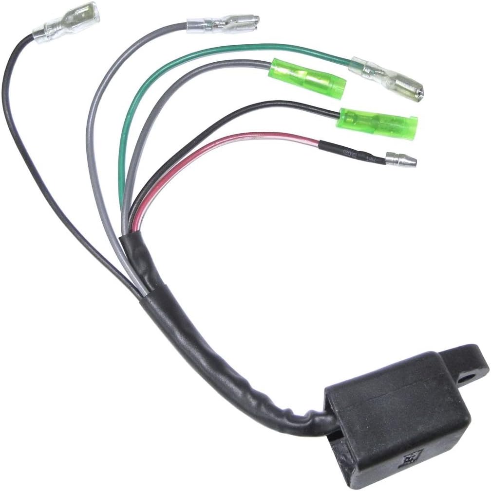
New Cdi Unit Assembly Box Ignition Yamaha Et650 And Et950 Generators Generators Home Garden

Cdi Capacitor Discharge Ignition Circuit Demo Ignition Coil Circuit Diagram Capacitor

Pin On Cdi Circuit Diagram

Cdi Motorcycle Wiring Diagram And Cdi Diagram Wiring Diagrams Folder Circuit Diagram Electrical Diagram Bike Restoration
Image Result For Gy6 Cdi Wiring Diagram Electrical Diagram Electrical Wiring Diagram Electrical Circuit Diagram

Pin On Cdi Wiring

5 Pin Cdi Wiring Diagram Mediapickle Diagram Electrical Diagram Wire

Cdi Circuit Diagram Motorcycle And Yamaha Yzrr Diagram Cdi Box Wiring Schematics Online Motorcycle Wiring Circuit Diagram Electrical Diagram

Dc Cdi Schematic Updated Techy At Day Blogger At Noon And A Hobbyist At Night Circuit Diagram Electrical Circuit Diagram Electrical Diagram
0 Response to "CDI UNIT ASSEMBLY BOX IGNITION ET950 SCHEMATIC CIRCUIT DIAGRAM"
Post a Comment